jueves, 28 de julio de 2016

Mechanical from scratch using Dynamo [Part 2]

fromcadtorevit-02
Today I'll explain the node we have created to generate ducts in Revit using lines coordinates from a cad file.
We will use the Revit API method Document.NewDuct Method (XYZ, XYZ, DuctType), which needs 3 parameters:
2 XYZ : (Autodesk.Revit.DB.XYZ) for the first and second point of the duct.
DuctType: (Autodesk.Revit.DB.Mechanical.DuctType) The type of the duct.
Disclaimer: Parts of the code below has been written using examples from the Dynamo Forum. We use those part to tie our code.
First you have to import all libraries needed to run the python script inside Dynamo.
import clr
# Import DocumentManager and TransactionManager
clr.AddReference('RevitServices')
import RevitServices
from RevitServices.Persistence import DocumentManager
from RevitServices.Transactions import TransactionManager
# Import RevitAPI
clr.AddReference('RevitAPI')
import Autodesk
# Import Revit Nodes
clr.AddReference("RevitNodes")
import Revit
# Import from Revit DB and all its parts
from Autodesk.Revit.DB import *
# Import from Revit Creation where the Create.NewDuct class is.
from Autodesk.Revit.Creation import *
# Import ToProtoType, ToRevitType geometry conversion extension methods
clr.ImportExtensions(Revit.GeometryConversion)

Then we define Current document in order to avoid calling the function by its full class name.

#Defining Current document
doc = DocumentManager.Instance.CurrentDBDocument

We need to read a cvs file and split it into strings. We also need to remove first and last row of the csv because they contains no numeric data - first line is the header of the csv and the last is empty.


#Konrad K Sobon's code from http://goo.gl/D4v6LU
#Split single string at line breaks into a list of strings
xyzList = IN[0].rsplit("\n")
# Cull the first line, which is header
del xyzList[0]
# Cull the last line, which is blank
del xyzList[len(xyzList)-1]


#Create empty list for points x and y
x = []
y = []

Asking for an input for Duct Type but no entry is needed from outside the script.

#Define Ducttype but not need to be provided by user,
# it will the first it finds
Ducttype = IN[1]

This is the part that makes the trick. First iterating over the xzy list to split it into strings. Then we need create points and append it to lists x and y.


#Iterate over list using Konrad K Sobon list to points script
for xyz in xyzList:
    tpt = xyz.rsplit(',')
    #convert first coord to points and to mm, as revit api
    #works with decimal feets you need to divide the float into 304.8 to mantain mm
    x.append(Autodesk.Revit.DB.XYZ((float(tpt[0])/304.8),(float(tpt[1])/304.8),(float(tpt[2])/304.8)).ToPoint())
    #convert second coord to points and in to mm
    y.append(Autodesk.Revit.DB.XYZ((float(tpt[3])/304.8),(float(tpt[4])/304.8),(float(tpt[5])/304.8)).ToPoint())

Printing x and y point list to check numbers after running the script.


#Print x & y points created
OUT = x,y

Once we have the list of points we need to iterate again and convert each point into XYZ which is needed by the NewDuct method. Note that the method should be contained in a transaction in order to create the duct in Revit.


#Iterate over list using Konrad K Sobon list to points script
for xyz in xyzList:
    tpt = xyz.rsplit(',')
    #convert first coord to points and to mm, as revit api
    #works with decimal feets you need to divide the float into 304.8 to mantain mm
    x.append(Autodesk.Revit.DB.XYZ((float(tpt[0])/304.8),(float(tpt[1])/304.8),(float(tpt[2])/304.8)).ToPoint())
    #convert second coord to points and in to mm
    y.append(Autodesk.Revit.DB.XYZ((float(tpt[3])/304.8),(float(tpt[4])/304.8),(float(tpt[5])/304.8)).ToPoint())

And it's ready.


dynamo-revit
Now we need to feed it with a csv containing the coordinates of the lines. This should create one duct for each couple of points.
dynamo
Node showing X and Y list of points from a CSV file
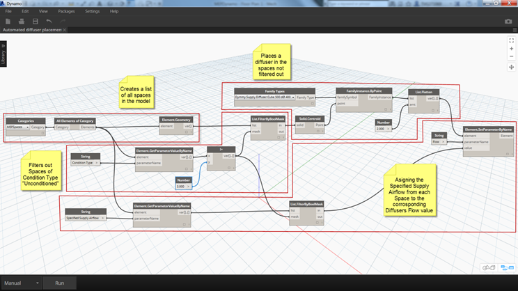
In the next post we'll explain how to model the diffusers in place using blocks coordinates from a cad file.
If you have any problems, comments or even corrections for us, leave your comments and we'll be glad to answer them.

Mechanical from scratch using Dynamo [Part 1]

fromcadtorevit-02
I would like to share with you a project where I'll try to create an HVAC system from a CAD sketch into Revit using Dynamo. This is not meant to be a new procedure to design mechanical systems more than a study of Dynamo capabilities on MEP modeling.
For this I've created this milestones/steps I'll try to accomplish on the next posts :
  1. Model a simple building on Revit and export to CAD.
  2. Sketch an HVAC layout with a supply system and a few diffusers.
  3. Export the location of the elements back to Revit using Dynamo.
  4. Change the sizes of the elements according to the flow needed on each room.
  5. Tag all elements having in count it's locations and sizes.
On this post I'll talk about the state of arts of the tools
  • My own Dynamo Node to create ducts from lines (still in beta but I'll publish it as soon as I could). Right now it only use 2 points to create a single duct but I'm trying to make it work using several points extracted from lines of a cad file using DataExtraction command.
CreateDuct node
CreateDuct node Beta
  • Node FamilyInstancebyPoint to locate the air terminals using the coordinates extracted from the cad files, as previously using DataExtraction command from Autocad.
    Family instance by point
    Family instance by point
  • Change diffusers flows according to room volume. The idea is to use the work on this node to detect how many diffusers are in the room and slip the flow on each one based on the room air volume
    http://autodesk.typepad.com/bimtoolbox/2015/07/automated-diffuser-placement-in-early-stage-mep-design.html
    Automated diffuser placement in early stage MEP design by Thomas Gregersen
  •  Konrad "Create annotations tag" node to place the tags on the elements according the sizes and orientation following a tagging standard.
    Dimitar Venkov example using Konrad
    Dimitar Venkov example using Konrad's node
As this will be an inductive study, I can't guaranty the success of the project but on the next posts I'll continue sharing my learned lessons using all these tools.
Pick anything you need and share, but please respect others authors rights.
To Be Continued...

Published first at https://scaleid.wordpress.com/2015/08/29/mechanical-from-scratch-using-dynamo/

Curve Section in Revit

First of all, right now there is no way to create a curved section in Revit even through the API., sorry! But there is a way to fake it.

Using Dynamo we could create a series of sections following a curve in the model or even a model line. For this we’ll use Luke Johnson’s Bakery package which contains the node “Revit Section View at Line”. The node uses a Revit Line as path to create a section in the model.

First thing we need is to get our Revit Line. We’ve two ways of doing it, using a Model Line or an edge of a Revit Element.

Model Line:
Using the node “Select Model Element” we’ll select the Model Line and translate it into a Dynamo Curve with “Element.Geometry”.

Select Model Element + Element.Geometry
Edge of a Revit Element:
Select the edge you want with the node “Select Edge”. No need to convert it because Dynamo understands it’s a Curve type.
Select Edge
Now that we have the curve we need to split it in curve chords. More segments we have, more detailed is the curve section we want to create.
We'll split the curve using "Curve.SplitByParameter". It needs a list of 1/n numbers to divide the curve. For this we create a list from 0 to 1 - start and end of the curve - and the the parts we want to split it. It should be written as follows.


0..1..1/x;

Curve.SplitByParameter
Now that we have our curves we need to create the lines for the section paths. With the end points of the curves we make a line by start and end points and then we use it to create the model line.

Create a model line with the ends of the curves

Now we are ready to create the sections with "Revit Section View at Line" node. By default it will create a section with 3000 units height and 100 Depth. You could change it as you need.


The final step is to erase the model lines we've created using "Tool.Eraser"

As final result we will get a series of sections following the curve. Just need to place them in a sheet and we are ready to go.


Here you will find the dyn file for you to use, I've added a formula with a boolean to be able to choose if use a model line or an edge to get the curve